The original article by Thomas Petazzoni can be found in his STM32MP1 blog.
Achtung
- Ausgangsbasis sind die Vorarbeiten aus Lab 3
- Bei Buildroot mit stm32mp157c-dk2.dts konfigurieren
Introduction
In Linux, both display controllers and GPUs are managed by a Linux kernel subsystem called DRM, for Direct Rendering Manager. The DRM drivers are located in drivers/gpu/drm in the Linux kernel source code. If the hardware also has a GPU in addition to the display controller, then the most significant part of handling the GPU is done in user-space libraries implementing OpenGL. In the open-source world, the de-facto standard OpenGL implementation is Mesa3D, which has support for a number of different GPUs. From a GPU driver perspective, the kernel mainly serves as a way for the user-space OpenGL library to allocate buffers and send commands to the GPU.
The STM32MP15 has both a display controller and a GPU, but in this blog post, we are only going to make use of the display controller. The Linux kernel DRM driver used for the display controller of the STM32MP15 is in drivers/gpu/drm/stm. The driver can be enabled using the CONFIG_DRM_STM kernel configuration option.
In addition, the display panel used on the STM32MP15 Discovery Kit is connected to the SoC using the MIPI DSI interface. The STM32MP15 SoC contains a DSI encoder hardware block from Synopsys, and a glue driver for the DSI encoder is available in drivers/gpu/drm/stm/dw_mipi_dsi-stm.c and can be enabled using the CONFIG_DRM_STM_DSI option.
It turns out that the kernel configuration file does have both of these options enabled, as well as the option providing support for the specific DSI display panel used on the Discovery board:
CONFIG_DRM=y
CONFIG_DRM_STM=y
CONFIG_DRM_STM_DSI=y
CONFIG_DRM_PANEL_ORISETECH_OTM8009A=y
The user-space interface of DRM is detailed in its documentation. Typical applications do not use directly this interface, and instead rely on a display stack in user-space such as X.org or Wayland, or directly on a graphical toolkit like Qt.
In addition, the DRM subsystem implements a compatibility layer that emulates the Linux framebuffer user-space interface, as documented in framebuffer.txt. This allows to support older applications/libraries that don’t use DRM directly.
In our case, we are going to use the Qt graphical toolkit, and on embedded Linux systems, it has four main display backends: eglfs (which requires an OpenGL/EGL graphics stack), linuxfb (which uses a simple legacy framebuffer interface), wayland (for Wayland, obviously) and xcb (for X.org). To keep things simple and because we don’t require OpenGL support, we will use the linuxfb backend.
Touch panel support in the Linux kernel
The Linux kernel has a subsystem called input for all input devices, such as keyboards, mice, touchscreens, joysticks and more. Its user-space interface is described in details in the kernel documentation, and this interface is used by most display stacks in user-space. For example, Qt supports itthrough the backend called evdev.
In terms of hardware, the Discovery Kit display panel integrates a touch panel that uses a Focaltech FT6236 controller, connected over I2C. The Device Tree describes this touch panel device as follows:
&i2c1 {
        touchscreen@2a {
                compatible = "focaltech,ft6236";
                reg = <0x2a>;
                interrupts = <2 2>;
                interrupt-parent = <&gpiof>;
                interrupt-controller;
                touchscreen-size-x = <480>;
                touchscreen-size-y = <800>;
                status = "okay";
        };
};
The corresponding driver in the Linux kernel is drivers/input/touchscreen/edt-ft5x06.c, which can be enabled using the CONFIG_TOUCHSCREEN_EDT_FT5X06 kernel configuration option.
The input subsystem, its evdev interface, and the specific driver for our touch panel are all already enabled in the kernel configuration :
CONFIG_INPUT_EVDEV=y
CONFIG_INPUT_TOUCHSCREEN=y
CONFIG_TOUCHSCREEN_EDT_FT5X06=y
Basic testing of the display and touch panel
To test the touch panel and display, we can start with very simple tools instead of using directly a complex graphical stack. The tools we recommend to use are:
- The evtest program from the project of the same name. It allows to dump input events from any input device.
- The modetest program that comes from the libdrm project. It allows to test a display by showing some pre-defined pictures.
Let’s add those two software components in our Buildroot configuration: go to menuconfig, and enable the BR2_PACKAGE_EVTEST, BR2_PACKAGE_LIBDRM and BR2_PACKAGE_LIBDRM_INSTALL_TESTS options. Restart the build of the Buildroot system by running make, and once the build has completed, write the new SD card image to your SD card.
On the system, let’s have a look at available input device (output edited to fit in the blog post):
# ls -l /sys/class/input/
event0 -> ...platform/soc/40012000.i2c/i2c-0/0-002a/input/input0/event0
event1 -> ...platform/soc/5c002000.i2c/i2c-2/2-0033/5c002000.i2c:stpmic@33:onkey/input/input2/event1
input0 -> ...platform/soc/40012000.i2c/i2c-0/0-002a/input/input0
input2 -> ...platform/soc/5c002000.i2c/i2c-2/2-0033/5c002000.i2c:stpmic@33:onkey/input/input2
So input0 is our touch panel (connected on I2C bus 0, at address 0x2A), and event0 is its evdev user-space interface. This evdev interface is accessible through the /dev/input/event0 device file:
# ls -l /dev/input/event0
crw-------    1 root     root       13,  64 Jan  1  1970 /dev/input/event0
Now we can run evtest. With no arguments, it shows the list of available input devices, their name, and allows use to chose the one we would like to test:
# evtest
No device specified, trying to scan all of /dev/input/event*
Available devices:
/dev/input/event0:	generic ft5x06 (11)
/dev/input/event1:	pmic_onkey
Select the device event number [0-1]: 0
Once evtest is running, press the touch panel, and you will see events reported like this:
Event: time 946685148.736402, type 3 (EV_ABS), code 57 (ABS_MT_TRACKING_ID), value 0
Event: time 946685148.736402, type 3 (EV_ABS), code 53 (ABS_MT_POSITION_X), value 259
Event: time 946685148.736402, type 3 (EV_ABS), code 54 (ABS_MT_POSITION_Y), value 428
Event: time 946685148.736402, type 1 (EV_KEY), code 330 (BTN_TOUCH), value 1
Event: time 946685148.736402, type 3 (EV_ABS), code 0 (ABS_X), value 259
Event: time 946685148.736402, type 3 (EV_ABS), code 1 (ABS_Y), value 428
These events show the coordinates of the press, and the actual press event (BTN_TOUCH).
With the touch panel working, let’s move on to the display. In fact, you know the display is already working: the fbcon kernel driver provides a console over the framebuffer, which is why you are seeing the Linux kernel messages on the screen. Nevertheless, let’s use the modetest program from libdrm. Without any argument, it just prints out some details about the available display hardware. First the encoders:
...
Encoders:
id	crtc	type	possible crtcs	possible clones
28	0	DPI	0x00000001	0x00000000
30	33	DSI	0x00000001	0x00000000
So the display controller has two encoders: one with a DPI interface (i.e parallel RGB interface) and one with a (MIPI) DSI interface.
Then, we have the list of connectors:
Connectors:
id	encoder	status		name		size (mm)	modes	encoders
29	0	disconnected	HDMI-A-1       	0x0		0	28
[..]
31	30	connected	DSI-1          	52x86		1	30
  modes:
	name refresh (Hz) hdisp hss hse htot vdisp vss vse vtot)
  480x800 50 480 578 610 708 800 815 825 839 29700 flags: ; type: preferred, driver
We have a HDMI connector, which can be used with the encoder of id 28, that is the DPI encoder. Indeed, the RGB parallel interface of the STM32 processor is fed on the board into an HDMI transceiver, that goes out with HDMI signals on connector CN9. So from the point of view of the SoC, it is a parallel RGB interface, but thanks to the HDMI transceiver on the Discovery board, it is in fact usable as an HDMI connector.
The second connector is the DSI connector, which can be used with encoder of id 30, i.e the DSI encoder, which makes sense.
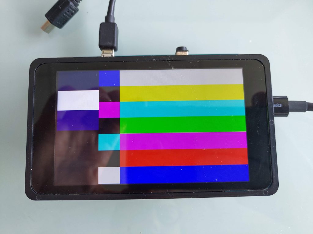
So let’s ask modetest to display its test picture on the DSI connector, which has id 31. The DSI panel resolution is 480×800, so we’ll use the following command:
# modetest -s 31:480x800
And voilà:
Now if we plug an HDMI screen to the HDMI connector, the modetest output about connector 29 changes as the connector is no longer disconnected:
...
| Codeblock | ||||||
|---|---|---|---|---|---|---|
| ||||||
# modetest
trying to open device 'i915'...failed
trying to open device 'amdgpu'...failed
trying to open device 'radeon'...failed
trying to open device 'nouveau'...failed
trying to open device 'vmwgfx'...failed
trying to open device 'omapdrm'...failed
trying to open device 'exynos'...failed
trying to open device 'tilcdc'...failed
trying to open device 'msm'...failed
trying to open device 'sti'...failed
trying to open device 'tegra'...failed
trying to open device 'imx-drm'...failed
trying to open device 'rockchip'...failed
trying to open device 'atmel-hlcdc'...failed
trying to open device 'fsl-dcu-drm'...failed
trying to open device 'vc4'...failed
trying to open device 'virtio_gpu'...failed
trying to open device 'mediatek'...failed
trying to open device 'meson'...failed
trying to open device 'pl111'...failed
trying to open device 'stm'...done
Encoders:
id      crtc    type    possible crtcs  possible clones
28      0       DPI     0x00000001      0x00000000
30 33 DSI 0x00000001 0x00000000 |
So the display controller has two encoders:
- one with a DPI interface (i.e parallel RGB interface) and..
- one with a (MIPI) DSI interface.
Then, we have the list of connectors:
| Codeblock | ||||||
|---|---|---|---|---|---|---|
| ||||||
Connectors:
id      encoder status          name            size (mm)       modes   encoders
29      0       connected       HDMI-A-1        520x320         5       28
  modes:
        index name refresh (Hz) hdisp hss hse htot vdisp vss vse vtot)
  #0 1280x720 60.00 1280 1390 1430 1650 720 725 730 750 74250 flags: phsync, pvsync; type: driver
  #1 1280x720 60.00 1280 1390 1430 1650 720 725 730 750 74250 flags: phsync, pvsync; type: driver
  #2 800x600 75.00 800 816 896 1056 600 601 604 625 49500 flags: phsync, pvsync; type: driver
  #3 720x480 59.94 720 736 798 858 480 489 495 525 27000 flags: nhsync, nvsync; type: driver
  #4 720x480 59.94 720 736 798 858 480 489 495 525 27000 flags: nhsync, nvsync; type: driver
  props:
        1 EDID:
                flags: immutable blob
                blobs:

                value:
                        00ffffffffffff0009d10a7845540000
                        1d120103803420782ec5c4a3574a9c23
                        124f52a56b807100810095008180b300
                        a940d1000101283c80a070b023403020
                        360007442100001a000000ff00463738
                        30303937345a4c300a20000000fd0032
                        551f5e11000a202020202020000000fc
                        0042656e51204732343030570a2001e6
                        02031af14604900301850766030c0010
                        00008301000023090707011d007251d0
                        1e206e285500c48e2100001f011d8018
                        711c1620582c2500c48e2100009e8c0a
                        d08a20e02d10103e9600c48e21000019
                        023a801871382d40582c4500c48e2100
                        0006d60980a020e02d1008602200128e
                        2108081800000000000000000000002c
        2 DPMS:
                flags: enum
                enums: On=0 Standby=1 Suspend=2 Off=3
                value: 0
        5 link-status:
                flags: enum
                enums: Good=0 Bad=1
                value: 0
        6 non-desktop:
                flags: immutable range
                values: 0 1
                value: 0
        19 CRTC_ID:
                flags: object
                value: 0
31      30      connected       DSI-1           52x86           1       30
  modes:
        index name refresh (Hz) hdisp hss hse htot vdisp vss vse vtot)
  #0 480x800 50.00 480 578 610 708 800 815 825 839 29700 flags: ; type: preferred, driver
  props:
        1 EDID:
                flags: immutable blob
                blobs:

                value:
        2 DPMS:
                flags: enum
                enums: On=0 Standby=1 Suspend=2 Off=3
                value: 0
        5 link-status:
                flags: enum
                enums: Good=0 Bad=1
                value: 0
        6 non-desktop:
                flags: immutable range
                values: 0 1
                value: 0
        19 CRTC_ID:
                flags: object
                value: 33

CRTCs:
id      fb      pos     size
33      41      (0,0)   (480x800)
  #0 480x800 50.00 480 578 610 708 800 815 825 839 29700 flags: ; type: preferred, driver
  props:
        20 ACTIVE:
                flags: range
                values: 0 1
                value: 1
        21 MODE_ID:
                flags: blob
                blobs:

                value:
                        04740000e00142026202c40200002003
                        2f033903470300003200000000000000
                        48000000343830783830300000000000
                        00000000000000000000000000000000
                        00000000
        18 OUT_FENCE_PTR:
                flags: range
                values: 0 18446744073709551615
                value: 0
        25 GAMMA_LUT:
                flags: blob
                blobs:

                value:
        26 GAMMA_LUT_SIZE:
                flags: immutable range
                values: 0 4294967295
                value: 256

Planes:
id      crtc    fb      CRTC x,y        x,y     gamma size      possible crtcs
32      33      41      0,0             0,0     0               0x00000001
  formats: AR24 XR24 RG24 RG16 AR15 XR15 AR12 XR12 C8
  props:
        7 type:
                flags: immutable enum
                enums: Overlay=0 Primary=1 Cursor=2
                value: 1
        16 FB_ID:
                flags: object
                value: 41
        17 IN_FENCE_FD:
                flags: signed range
                values: -1 2147483647
                value: -1
        19 CRTC_ID:
                flags: object
                value: 33
        12 CRTC_X:
                flags: signed range
                values: -2147483648 2147483647
                value: 0
        13 CRTC_Y:
                flags: signed range
                values: -2147483648 2147483647
                value: 0
        14 CRTC_W:
                flags: range
                values: 0 2147483647
                value: 480
        15 CRTC_H:
                flags: range
                values: 0 2147483647
                value: 800
        8 SRC_X:
                flags: range
                values: 0 4294967295
                value: 0
        9 SRC_Y:
                flags: range
                values: 0 4294967295
                value: 0
        10 SRC_W:
                flags: range
                values: 0 4294967295
                value: 31457280
        11 SRC_H:
                flags: range
                values: 0 4294967295
                value: 52428800
34      0       0       0,0             0,0     0               0x00000001
  formats: AR24 RG24 RG16 AR15 AR12 C8
  props:
        7 type:
                flags: immutable enum
                enums: Overlay=0 Primary=1 Cursor=2
                value: 0
        16 FB_ID:
                flags: object
                value: 0
        17 IN_FENCE_FD:
                flags: signed range
                values: -1 2147483647
                value: -1
        19 CRTC_ID:
                flags: object
                value: 0
        12 CRTC_X:
                flags: signed range
                values: -2147483648 2147483647
                value: 0
        13 CRTC_Y:
                flags: signed range
                values: -2147483648 2147483647
                value: 0
        14 CRTC_W:
                flags: range
                values: 0 2147483647
                value: 0
        15 CRTC_H:
                flags: range
                values: 0 2147483647
                value: 0
        8 SRC_X:
                flags: range
                values: 0 4294967295
                value: 0
        9 SRC_Y:
                flags: range
                values: 0 4294967295
                value: 0
        10 SRC_W:
                flags: range
                values: 0 4294967295
                value: 0
        11 SRC_H:
                flags: range
                values: 0 4294967295
                value: 0

Frame buffers:
id      size    pitch
|
We have a HDMI connector, which can be used with the encoder of id 31, that is the DPI encoder. Indeed, the RGB parallel interface of the STM32 processor is fed on the board into an HDMI transceiver, that goes out with HDMI signals on connector CN9. So from the point of view of the SoC, it is a parallel RGB interface, but thanks to the HDMI transceiver on the Discovery board, it is in fact usable as an HDMI connector.
The second connector is the DSI connector, which can be used with encoder of id 30, i.e the DSI encoder, which makes sense.
So let’s ask modetest to display its test picture on the DSI connector, which has id 30 for DSI panel resolution is 480×800, so we’ll use the following command:
# modetest -s 31:480x800
And voilà:
Now if we plug an HDMI screen to the HDMI connector, the modetest output about connector 29 changes as the connector is no longer disconnected:
| Codeblock | ||||||
|---|---|---|---|---|---|---|
| ||||||
Connectors:
id      encoder status          name            size (mm)       modes   encoders
29      0       connected       HDMI-A-1        520x320         5       28
  modes:
        index name refresh (Hz) hdisp hss hse htot vdisp vss vse vtot)
  #0 1280x720 60.00 1280 1390 1430 1650 720 725 730 750 74250 flags: phsync, pvsync; type: driver
  #1 1280x720 60.00 1280 1390 1430 1650 720 725 730 750 74250 flags: phsync, pvsync; type: driver
  #2 800x600 75.00 800 816 896 1056 600 601 604 625 49500 flags: phsync, pvsync; type: driver
  #3 720x480 59.94 720 736 798 858 480 489 495 525 27000 flags: nhsync, nvsync; type: driver
  #4 720x480 59.94 720 736 798 858 480 489 495 525 27000 flags: nhsync, nvsync; type: driver
  props:
        1 EDID:
                flags: immutable blob
                blobs:

                value:
                        00ffffffffffff0009d10a7845540000
                        1d120103803420782ec5c4a3574a9c23
                        124f52a56b807100810095008180b300
                        a940d1000101283c80a070b023403020
                        360007442100001a000000ff00463738
                        30303937345a4c300a20000000fd0032
                        551f5e11000a202020202020000000fc
                        0042656e51204732343030570a2001e6
                        02031af14604900301850766030c0010
                        00008301000023090707011d007251d0
                        1e206e285500c48e2100001f011d8018
                        711c1620582c2500c48e2100009e8c0a
                        d08a20e02d10103e9600c48e21000019
                        023a801871382d40582c4500c48e2100
                        0006d60980a020e02d1008602200128e
                        2108081800000000000000000000002c
        2 DPMS:
                flags: enum
                enums: On=0 Standby=1 Suspend=2 Off=3
                value: 0
        5 link-status:
                flags: enum
                enums: Good=0 Bad=1
                value: 0
        6 non-desktop:
                flags: immutable range
                values: 0 1
                value: 0
        19 CRTC_ID:
                flags: object
value: 0 |
So we can ask modetest to display a 1280×720 picture on the HDMI screen:
# modetest -s 29:1280x720
Enabling Qt5 support in Buildroot
Now that we have successfully tested the display and touchscreen, it is time to move on and use a powerful graphical toolkit for embedded Linux systems: Qt. Qt is already packaged in Buildroot, and therefore very easy to add to our system, including some examples. Simply enable the following options in your Buildroot configuration:
BR2_PACKAGE_QT5, which enables Qt as a whole, and automatically selects the core Qt module called qt5baseBR2_PACKAGE_QT5BASE_GUI, which enables GUI support in qt5base. The linuxfb backend is automatically selected, but provided the appropriate dependencies are enabled, other display backends can be enabled as well. In our case, we’ll use the linuxfb backend so the default selection will work for us.BR2_PACKAGE_QT5BASE_WIDGETS, which enables the Qt5 Widget library, which allows to easily write graphical applications with buttons, text boxes, drop down lists and other familiar graphical widgetsBR2_PACKAGE_QT5BASE_EXAMPLES, to enable the example Qt5 applicationsBR2_PACKAGE_QT5BASE_FONTCONFIG, to enable the fontconfig support in Qt. This allows Qt to discover the fonts available on our system to render text.BR2_PACKAGE_DEJAVU, which will provide one font to render text. Without this, Qt applications would run, but no text would be rendered
Once these options are enabled, restart the build with make and rewrite the new image to your SD card.
Test Qt5 application
All the Qt examples are installed in /usr/lib/qt/examples/, so you can try all of them. Let’s start with the analogclock for example:
# /usr/lib/qt/examples/gui/analogclock/analogclock -platform linuxfb
...
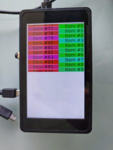
Then, another one
...
# /usr/lib/qt/examples/widgets/scroller/graphicsview/graphicsview -platform linuxfb
...
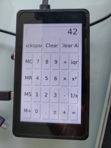
which allows to test the touch panel:
# /usr/lib/qt/examples/widgets/widgetsscroller/calculatorgraphicsview/calculatorgraphicsview -platform linuxfb
Filesystem size
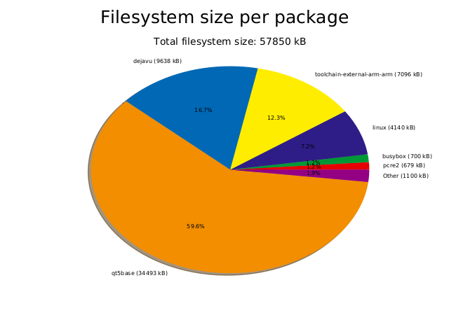
To conclude this article, let’s have a look at the size of our filesystem size. After a completely clean build (make clean all), Buildroot can generate a nice graph of the filesystem size using make graph-size. In our case, it generates the following graph:
...
And a more “complete” and useful application, which as you can see does not fit very well on a 480×800 screen in portrait mode, but also allows to use the touchscreen:
#
Filesystem size
To conclude this article, let’s have a look at the size of our filesystem size. After a completely clean build (make clean all), Buildroot can generate a nice graph of the filesystem size using make graph-size. In our case, it generates the following graph:
| View file | ||||
|---|---|---|---|---|
|


